PDF Design and Simulation of Electrocardiogram Circuit with Automatic Circuit Diagram To interface the AD8232 ECG Module with Arduino, make connections according to the given table/Circuit diagram. Use the Arduino IDE to upload this code. Go to tools>Serial Plotter in the Arduino IDE and set the baud rate to 9600. . You may view the results in the form of a graph on the Arduino IDE plotter after the code has been uploaded.

This tutorial is an in-depth guide on how to make your own simple EEG circuit. Along with monitoring brain wave concentration, the final circuit can also be used as an ECG, as a way to see your heartbeat trace. The circuit will use 3 electrodes - 2 to measure a voltage difference across your scalp, and one as a reference to ground.

Time ECG Monitoring System Using AD8232 and Arduino UNO Circuit Diagram
I made this circuit for general biopotential measurements, but once you figure out the specific signal you want to measure, you'll probably need to make more changes. For ECG, the amount of gain used is probably sufficient, but for EEG or a more sensitive signal, you'll probably need some more gain. I would recommend adding a few bandpass filters.
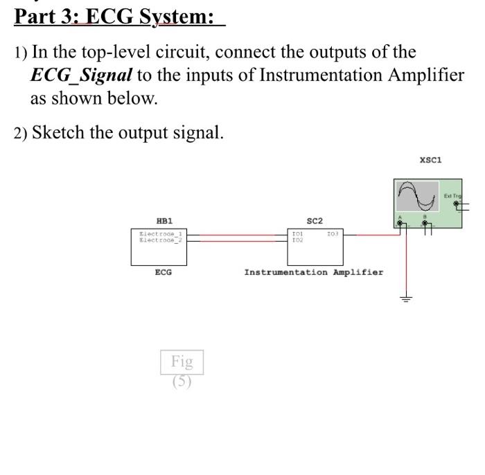
An electrocardiogram signal can be simulated using a waveform generator. Select the appropriate in-built ECG waveform function using the user interface. The signal should have a low amplitude input of 1 - 5 mV and a frequency of around 1.2 Hz. Connect the generator to the input terminal of the integrated circuit. The Arduino continuously samples the analog signal from the A0 pin, which represents the real-time ECG waveform. This signal is then converted from analog to digital format by the Arduino's ADC (Analog to Digital Converter) for further processing. The digitalized ECG data is transmitted to the computer via a USB connection.
Make Your Own Electrocardiogram (ECG) : 6 Steps Circuit Diagram
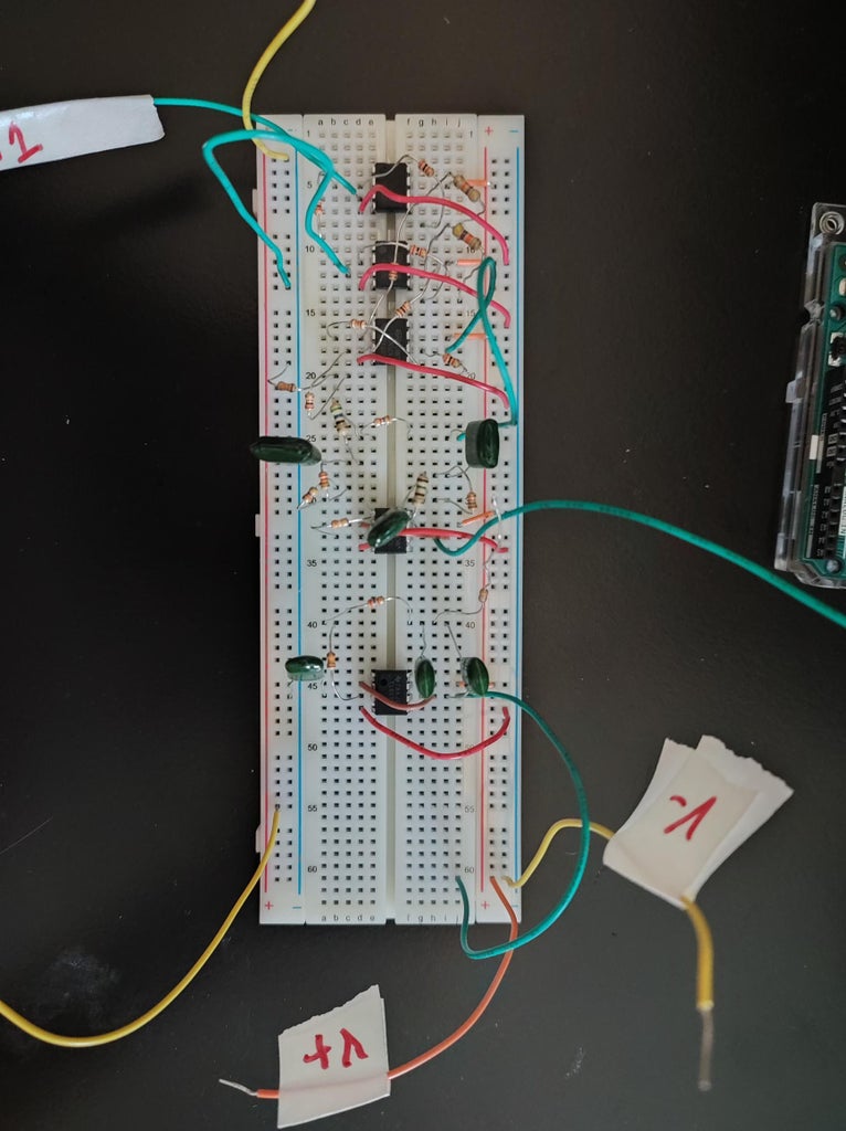
Featuring an instrumentation amplifier made up of three 741 op-amps and an assortment of resistors.#ecg #circuit
