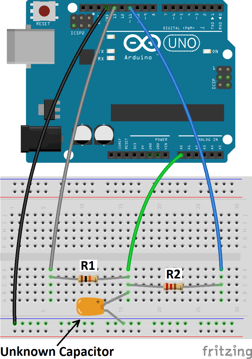
How can i make a easy op amp circuit Circuit Diagram By using the function micros(), we'll know how long the pulse is, and we'll calculate the resistance. The value of the resistor can be chosen freely. We'll take 1 MOhm for measuring low capacitance (nF range), and 10kOhm for higher capacitance (uF range). Otherwise, measurements in the uF range would take ages.

Good for lighting LED's, driving other circuits - useless for reading sensors. Additionally the pins can be HIGH (+5 volts), to charge the capacitor; or LOW (ground) to discharge the capacitor. Algorithm for capacitance meter sketch. Set discharge pin to INPUT (so it can't discharge the capacitor) Record the start time with millis()

6 Simple Capacitance Meter Circuits Explained Circuit Diagram
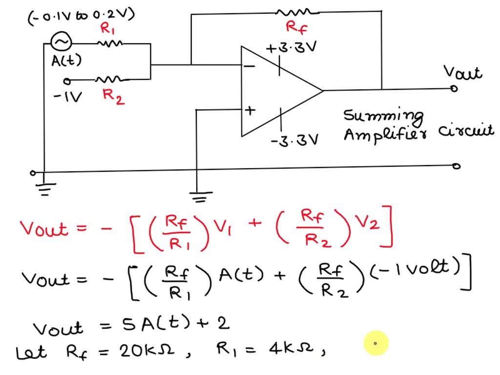
b) R1.Cf is not >> input period. Then you need to allow for R1 and know the frequency if you are calculating the gain. If you are simply making a capacitance meter, and you calibrate the scale with a known capacitor, and keep the frequency constant, then you can ignore their actual values.
Op amp IC1 is attached like a comparator, with its (+) input pin attached to R8, which fixes the reference voltage level. Prior to supplying power to the capacitance meter circuit, use a fine screwdriver to adjust the meter M1 needle precisely to the zero level. Position an accurately known capacitor around 0.5 and 1.0 µF at +/-5%. This
Capacitance Meter With Arduino and 741 Op Circuit Diagram
Switch ON the power supply - select a suitable position on S1 so that the deflection on the meter reads near about full scale. Fine tune VR1 to make the reading exactly full scale. Due to a linear behavior of the circuit, the readings will perfectly respond to other values of capacitors proportionately throughout the entire meter calibration.