Current sense circuit small current Circuit Diagram It is unlikely that any particular circuit shown will exactly meet the requirements for a specific design, but the suggestion of many circuit techniques and devices should prove useful. allow for very wide range current sensing. In this circuit a six decade range of current pulled from the circuit input terminal is converted to an output Current Sensing Tutorial: Introduction This project attempts to provide a brief review of the current sensing techniques underlying 2 common types of current sensors: the conventional DC current sensor and the hall-effect sensor. Breadboard 1 To provide a convenient workspace for the circuit . DC Motor 1 Acts as a load in the tested circuit

Current sensing example circuits - quiz 5. Overcurrent detection is used to: a) Alert when load current has exceeded a specified threshold b) Help ensure that electronic systems operate safely c) Help a control system decide if power needs to be turned off d) All of the above 6. The INA302 and INA303 are examples of: a) A current sense comparator

PDF Current Sensing Example Circuits Circuit Diagram
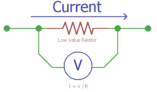
The idea is that you could build such a current sensor yourself and that's what this article is all about. The only hurdle is to measure low voltage drop. In the modules that I have dealt with so far, the shunt had a resistor of 0.1 ohms. Even with a fairly high current of, for example, an ampere, the voltage drop is just one hundred millivolts.
Assume that the required specifications of the low-side current detection circuit are as follows. Current sensing range: ILOADmin to ILOADmax = 30 A to 50 A Current sensing error: Err = 7% Current sensing frequency: fsense = 1 kHz Voltage drop at shunt resistor: ΔVSHUNTmax = 50 mV Maximum output voltage of the op-amp: VOmax = 3.3 V
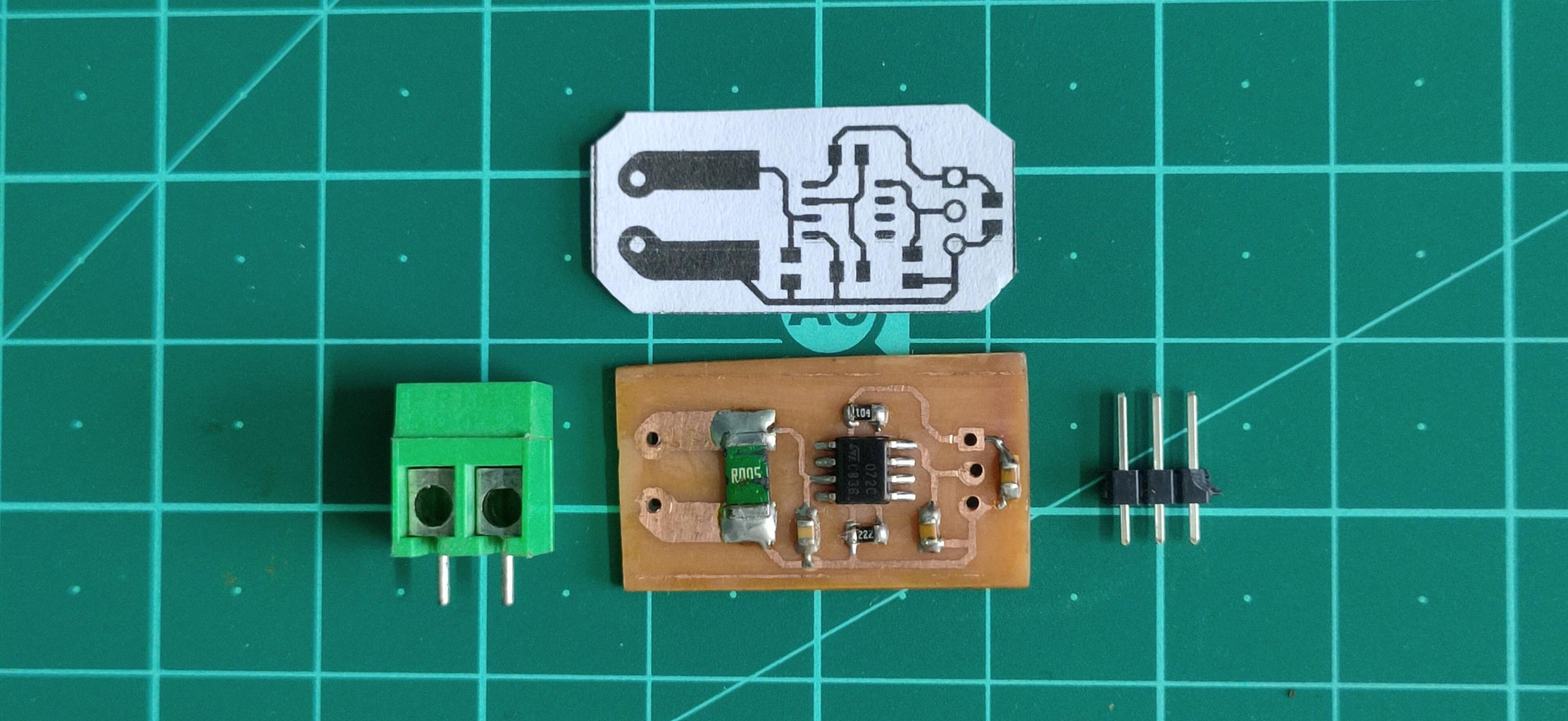
How to Build a Current Sensor Circuit Circuit Diagram
fundamentals of current sensing circuits. It introduces current sensing resistors, current sensing techniques and describes three typical high-side current sensing implementations, with their advantages and disadvan-tages. The other current sensing implementations are beyond the scope of this application note and reserved
